7.0.1.2 Class Activity Eigrp - Back to the Future
The EIGRP Metric has caused confusion for many network engineers trying to understand the protocol. This article will dive into what the metric is, and how to boil it down into its simplified form.
Formula and K-Values
EIGRP is a Cisco Proprietary routing protocol created in the 1980s. As such, Cisco was the only vendor that had the rights to implement said protocol. Until 1998 when Cisco released the specification as an IETF draft.
One of EIGRP's main benefits is being able to consider many different attributes when calculating a route's cost, or metric. Namely, EIGRP is one of the only routing protocols that can consider any combination of Bandwidth, Load, Delay, and Reliability into its cost calculation.
Each of these attributes are controlled by what is known as a K-value. These K-values each enable the consideration of one of the aforementioned attributes, as well as the scale to which the attribute is considered.
K1 = Bandwidth K2 = Load K3 = Delay K4 & K5 = Reliability
Each of these values are used in what EIGRP calls a Composite Metric formula. That formula is as follows:
EIGRP metric:
256 * { K1*BW + [(K2*BW)/(256-load)] + (K3*delay) } * { K5/(reliability+K4) }
It looks pretty complicated, but you can simplify it somewhat by rewriting it in a different format and breaking up each part with pretty colors:
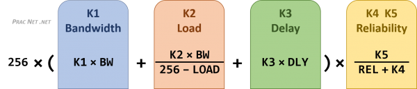
The K-values themselves are a number between 0 and 255. You can set each value independently based upon what you want considered in the cost calculation for each route. If in your routing domain you wish to not consider one of the attributes above, you can set the appropriate K-value to Zero. If you wish to consider an attribute, you can set the appropriate K-value to one.
Since the K-values can be any value up to 255, you also have the ability to scale how heavily a particular value is considered. For example, if you wish for Bandwidth to be considered twice as important as Delay, you can set the K1 value to 2, and the K3 value to 1. If you wish to consider Bandwidth and Delay in a 2:3 ratio, you can set K1 to 2, and K3 to 3. This is what gives EIGRP such flexibility in its cost comparison, you can choose which attributes and how important each attribute is to your routing domain.
It should be noted, however, that before two routers will become EIGRP neighbors, they must have matching K-values. Which makes sense, because if one router considers Delay as the utmost important, and the other considers Bandwidth as the utmost important, then they might disagree as to which path to a destination network is best.
EIGRP Default Metric
Despite how flexible the cost calculation is, most implementations of EIGRP just rely on the default K-values for their metric. The default K-values consider only Bandwidth and Delay, and ignore Load and Reliability.
There are two reasons Load and Reliability are not included in the default EIGRP metric:
First, EIGRP does not do periodic updates — only triggered updates. As a result, the values for Load and Reliability are calculated once when a route is first learned, but are not updated dynamically as an interface becomes more or less saturated. A change in Load/Reliability does not trigger a new EIGRP update.
Second, the Load and Reliability values are not a reflection of the full path's load and reliability, but instead only of the directly connected link.
As such, Cisco elected to only consider Bandwidth and Delay, and to weigh them equally, in their default EIGRP metric calculation. The default K-Values are K1 and K3 set to one, and K2, K4, and K5 set to zero.
We can plug the default K-values into the formula above to see how it can be simplified:
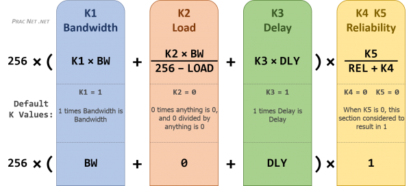
With the image above, we can simplify the complicated full EIGRP composite metric to just this:
256 × ( Bandwidth + Delay )
Which is much easier to manage than the full composite formula listed above
Calculating EIGRP Metrics
At this point, it would be wise to discuss how the Bandwidth value and Delay values are attained.
We will use the following topology:
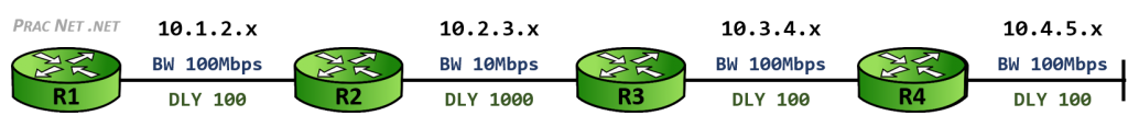
To keep it simple, we will use the Metric calculation for the 10.4.5.x network from the perspective or R4. The show interfaces command of R4 will give us our starting values:
R4# show interfaces FastEthernet 0/0 FastEthernet0/0 is up, line protocol is up Hardware is Gt96k FE, address is c204.8b8c.0000 (bia c204.8b8c.0000) Internet address is 10.4.5.4/24 MTU 1500 bytes, BW 100000 Kbit/sec, DLY 100 usec,
We will use these as an example to show you how the EIGRP metric is calculated.
Bandwidth Calculation
The Bandwidth value is based upon the minimum bandwidth link across the entire path. But because metric values in any routing protocol consider a lower value to be superior, a formula has to be used to convert a higher bandwidth to a lower resulting metrics. That formula is as follows:
Bandwidth = 10^7 / BW in Kbps
For R4, who is directly connected to the 10.4.5.0/24 network on a 100 Mbps link, the calculation would result in:
Bandwidth = 10,000,000 / 100,000 kbps = Bandwidth Value of 100
The Bandwidth Value of 100 will be plugged into our simplified EIGRP Metric formula we derived earlier.
Delay Calculation
Delay is supposed to be a calculation of the amount of time it takes a bit to be transmitted to an adjacent neighbor. But in reality it is simply a constant value based upon the interface bandwidth. However, since this factor is additive, it essentially works as a hop count. Or maybe we should say a smart hop count, since it also factors each hop's bandwidth.
In the output above, the DLY is displayed as a usec, which is a microsecond, or one millionth of a second. The delay value used in the EIGRP metric calculation is the delay in 10's of microseconds. So to calculate the Delay value, simply divide the DLY in the show interface command by 10.
For R4's interface above, you would get:
Delay = 100 usec / 10 = Delay Value of 10
The Delay Value of 10 will be plugged into our simplified EIGRP Metric formula we derived earlier.
Note that the delay in the metric calculation is the cumulative value along each hop to the target network. In this case, since R4 is directly connected to the 10.4.5.0/24 network, we can use the interface's delay directly in our formula.
The full table of delay values based upon bandwidth can be found here. This document lists each interface bandwidth in Kbps and its correlating delay value in picoseconds – one trillionth of a second.
For reference, the more commonly used values are in the table below, as well as the converted values for Mbps, bps, and usec.
| Interface Bandwidth | BW in bps | BW in Kbps | Delay Value | Delay in usec |
|---|---|---|---|---|
| 10 Mbps | 10,000,000 | 10,000 | 1,000,000 | 1,000 |
| 100 Mbps | 100,000,000 | 100,000 | 100,000 | 100 |
| 1 Gbps | 1,000,000,000 | 1,000,000 | 10,000 | 10 |
| 10 Gbps | 10,000,000,000 | 10,000,000 | 10,000 | 10 |
EIGRP Metric Calculation
We can use the resulting Bandwidth Value and Delay Value from above in the simplified EIGRP composite metric formula we deduced earlier:
256 × ( Bandwidth Value + Delay Value )
256 × ( 100 + 10 )
256 × 110 = 28160
We can compare this against R4's EIGRP topology table output for the 10.4.5.0/24 network to confirm we did everything correctly:
R4# show ip eigrp topology 10.4.5.0/24 IP-EIGRP (AS 99): Topology entry for 10.4.5.0/24 State is Passive, Query origin flag is 1, 1 Successor(s), FD is 28160 Routing Descriptor Blocks: 0.0.0.0 (FastEthernet0/0), from Connected, Send flag is 0x0 Composite metric is (28160/0), Route is Internal Vector metric: Minimum bandwidth is 100000 Kbit Total delay is 100 microseconds Reliability is 255/255 Load is 1/255 Minimum MTU is 1500 Hop count is 0
The Route metric is displayed in parenthesis as ( feasible_distance / reported_distance ) . The feasible distance is R4's total metric calculation to get to the target network. The reported distance is 0, since no router advertised this route to R4 — R4 was in fact directly connected to the network.
Remaining Routers
In order to go full circle, we will show you the calculation of the composite metric for R3, R2, and R1 to the same 10.4.5.0/24 network.
Notice the link between R2 and R3 is a 10Mbps link. We can use this to display the effect of the minimum path bandwidth being utilized as we study the route to 10.4.5.0/24 from R1, R2, and R3. For completeness, we will also display the calculation from R4 again, as well as place the same topology image below to spare you from continually scrolling back up.
R4 R3 R2 R1
R4# show ip eigrp topology 10.4.5.0/24 IP-EIGRP (AS 99): Topology entry for 10.4.5.0/24 State is Passive, Query origin flag is 1, 1 Successor(s), FD is 28160 Routing Descriptor Blocks: 0.0.0.0 (FastEthernet0/0), from Connected, Send flag is 0x0 Composite metric is (28160/0), Route is Internal Vector metric: Minimum bandwidth is 100000 Kbit Total delay is 100 microseconds Reliability is 255/255 Load is 1/255 Minimum MTU is 1500 Hop count is 0
Bandwidth Value = 10,000,000 / Minimum Path Bandwidth in Kbps Bandwidth Value = 10,000,000 / 100,000 Kbps = 100 Delay Value = Cumulative Delay in usec / 10 Delay Value = 100 usec / 10 = 10 Composite Metric = 256 × ( Bandwidth Value + Delay Value ) Composite Metric = 256 × ( 100 + 10 ) Composite Metric = 256 × 110 = 28160
R3# show ip eigrp topology 10.4.5.0/24 IP-EIGRP (AS 99): Topology entry for 10.4.5.0/24 State is Passive, Query origin flag is 1, 1 Successor(s), FD is 30720 Routing Descriptor Blocks: 10.3.4.4 (FastEthernet0/1), from 10.3.4.4, Send flag is 0x0 Composite metric is (30720/28160), Route is Internal Vector metric: Minimum bandwidth is 100000 Kbit Total delay is 200 microseconds Reliability is 255/255 Load is 1/255 Minimum MTU is 1500 Hop count is 1
Bandwidth Value = 10,000,000 / Minimum Path Bandwidth in Kbps Bandwidth Value = 10,000,000 / 100,000 Kbps = 100 Delay Value = Cumulative Delay in usec / 10 Delay Value = 200 usec / 10 = 20 Composite Metric = 256 × ( Bandwidth Value + Delay Value ) Composite Metric = 256 × ( 100 + 20 ) Composite Metric = 256 × 120 = 30720
R2# show ip eigrp topology 10.4.5.0/24 IP-EIGRP (AS 99): Topology entry for 10.4.5.0/24 State is Passive, Query origin flag is 1, 1 Successor(s), FD is 286720 Routing Descriptor Blocks: 10.2.3.3 (FastEthernet0/0), from 10.2.3.3, Send flag is 0x0 Composite metric is (286720/30720), Route is Internal Vector metric: Minimum bandwidth is 10000 Kbit Total delay is 1200 microseconds Reliability is 255/255 Load is 1/255 Minimum MTU is 1500 Hop count is 2
Bandwidth Value = 10,000,000 / Minimum Path Bandwidth in Kbps Bandwidth Value = 10,000,000 / 10,000 Kbps = 1000 Delay Value = Cumulative Delay in usec / 10 Delay Value = 1200 usec / 10 = 120 Composite Metric = 256 × ( Bandwidth Value + Delay Value ) Composite Metric = 256 × ( 1000 + 120 ) Composite Metric = 256 × 1120 = 286720
R1# show ip eigrp topology 10.4.5.0/24 IP-EIGRP (AS 99): Topology entry for 10.4.5.0/24 State is Passive, Query origin flag is 1, 1 Successor(s), FD is 289280 Routing Descriptor Blocks: 10.1.2.2 (FastEthernet0/1), from 10.1.2.2, Send flag is 0x0 Composite metric is (289280/286720), Route is Internal Vector metric: Minimum bandwidth is 10000 Kbit Total delay is 1300 microseconds Reliability is 255/255 Load is 1/255 Minimum MTU is 1500 Hop count is 3
Bandwidth Value = 10,000,000 / Minimum Path Bandwidth in Kbps Bandwidth Value = 10,000,000 / 10,000 Kbps = 1000 Delay Value = Cumulative Delay in usec / 10 Delay Value = 1300 usec / 10 = 130 Composite Metric = 256 × ( Bandwidth Value + Delay Value ) Composite Metric = 256 × ( 1000 + 130 ) Composite Metric = 256 × 1130 = 289280
Notice how the composite metric gets really large (aka, less preferred) at R2 due to the 10 Mbps link.
If you are able to follow along with the calculation in each of the tabs above, then you are now a master of the EIGRP metric. Except for maybe one last confusing, metric-related piece of knowledge: the feasibility condition. But don't worry, that is covered in another article.
7.0.1.2 Class Activity Eigrp - Back to the Future
Source: https://www.practicalnetworking.net/stand-alone/eigrp-metric/
0 Response to "7.0.1.2 Class Activity Eigrp - Back to the Future"
Postar um comentário